Somehow turning Chromebooks into a Videowall
this project took way too long
The Idea
Running the 'Coding Club' at school, our mentor, Mr. Bush, suggested creating a "Videowall" out of Chromebooks the school was going to throw away. We thought it was just another teacher with a fanciful tech idea with no idea how hard it would be to execute.
This project was a collaboration with my friend Varun Biniwale. I was responsible for the hardware, and he designed the incredible software — see his blog to learn about the unexpectedly complex software needed to run these dismantled computers.
We got started on the project in late 2021 despite the difficulty of the task ahead of us, mainly because our mentor was one of our favorite teachers.
The first part we started on was the software, as it seemed like the easiest, and frankly, like the only possible part of the project at the time. What we wanted to do was have one long video playing across multiple screens. While connecting all of the Chromebook screens to one computer was an option, we had no clue how to interface with displays since we couldn't just plug in an HDMI cable, and thus we decided against this idea.
Pretty sure this is not how we are supposed to interface with the screens...
In the first few weeks, we spent our Monday afternoons trying to find existing software to synchronize videos across different computers. Our plan was to crop a wide video into smaller segments for each screen, giving the illusion of a single, continuous video. We experimented with Syncplay using VLC and looked at paid software such as Navori, but neither was exactly what we were looking for.
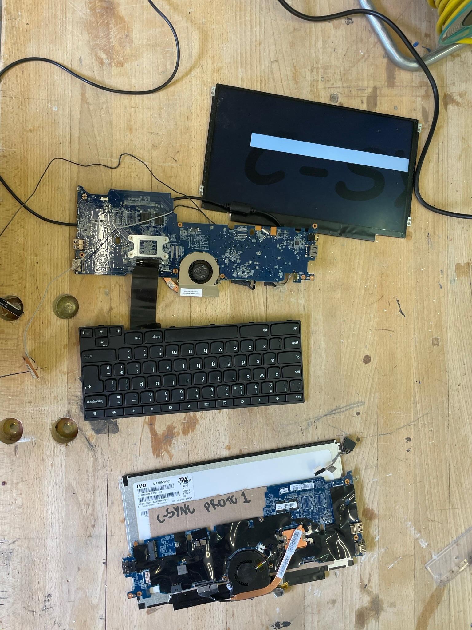
Giving up on existing software, Varun got to work on custom software to synchronize the video across multiple computers. He called it C-Sync after other synchronization technologies such as G-Sync, FreeSync, VSync, etc.
Of course we had to use Comic Sans.
This was only the start of the digital side of the project, and I again recommend you read about the insanely difficult task Varun had to actually make it run on the Chromebooks here.
The Physical Part
Now comes the part which was actually figuring out how to make the physical videowall.
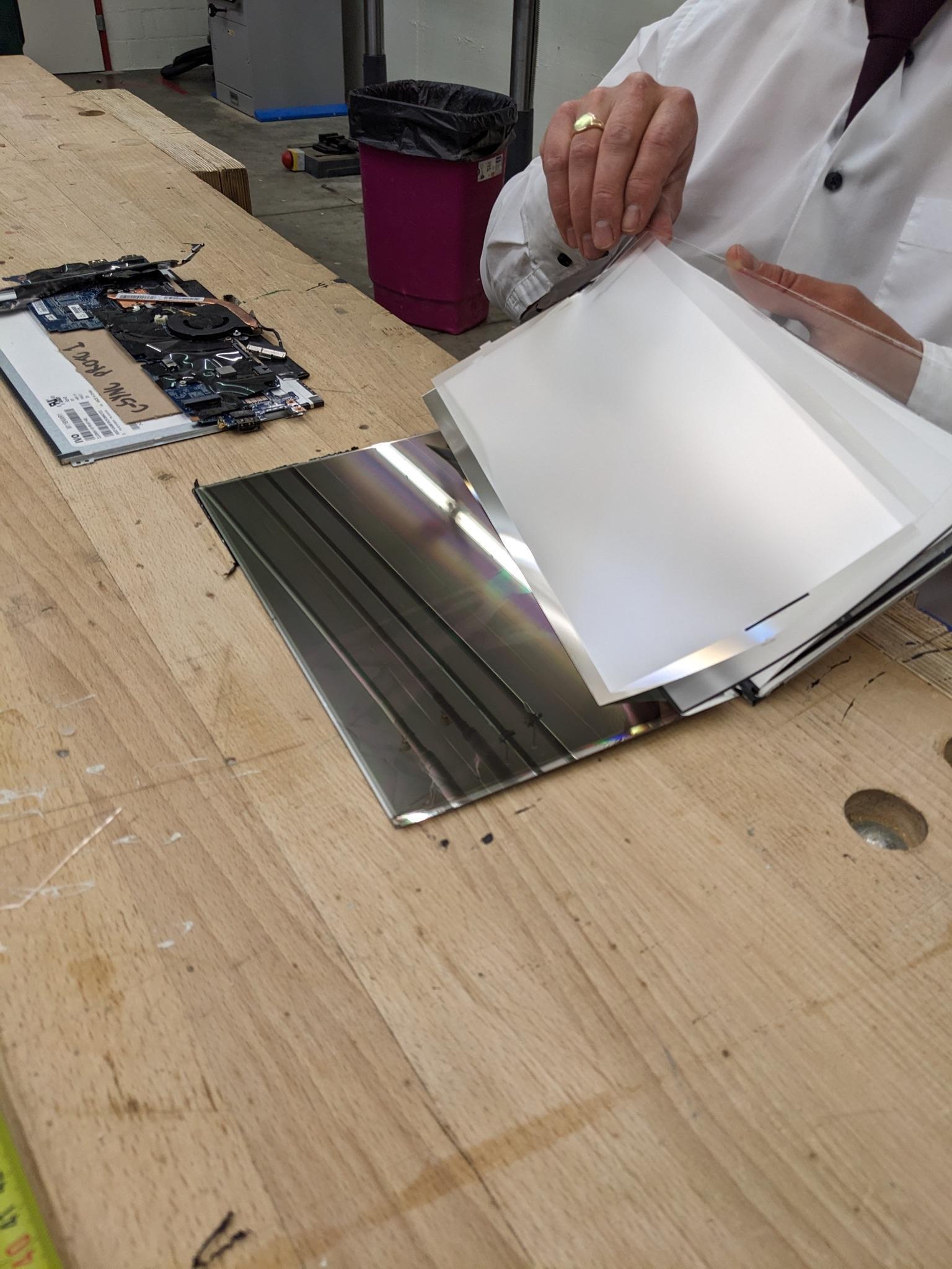
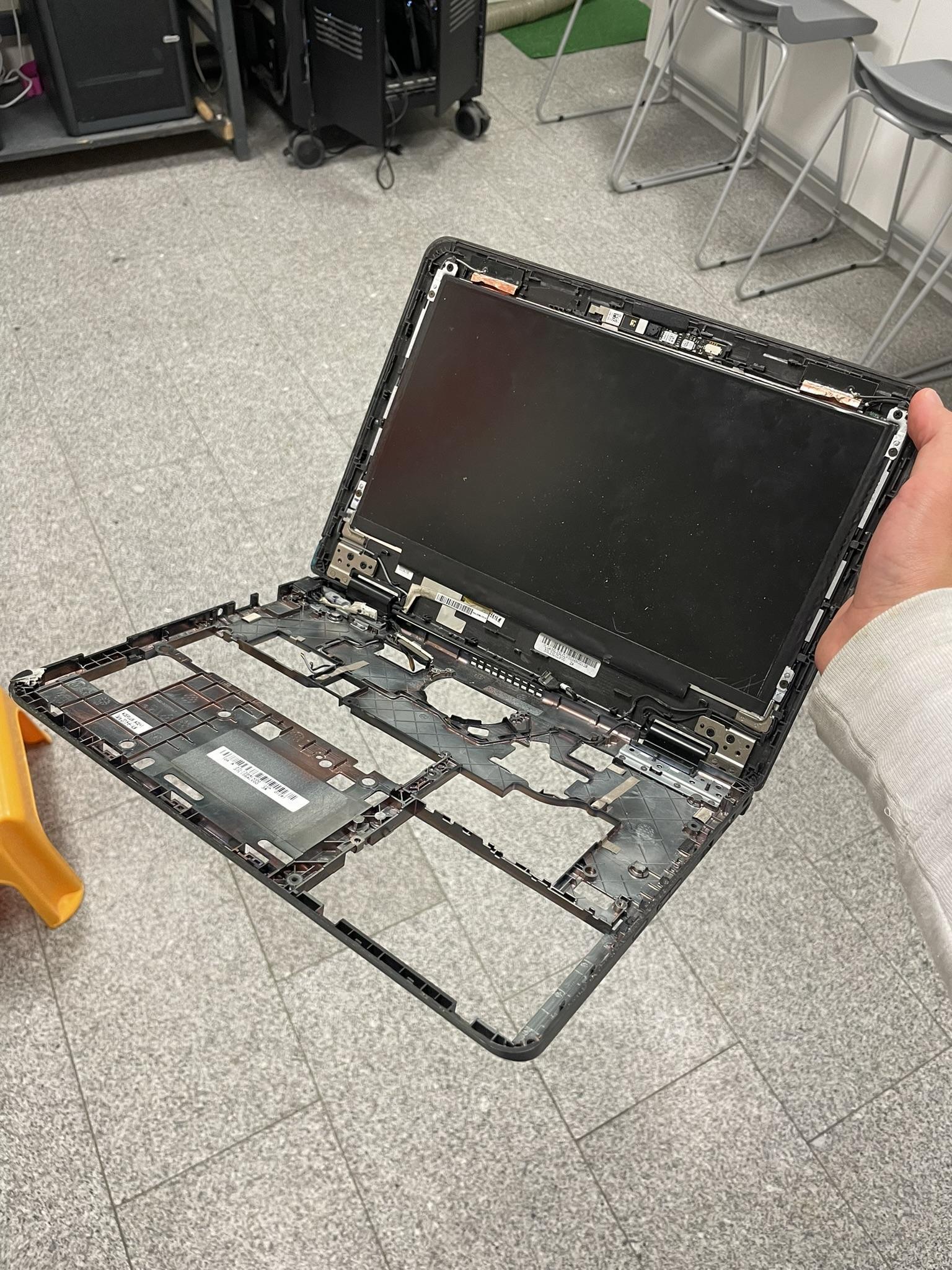
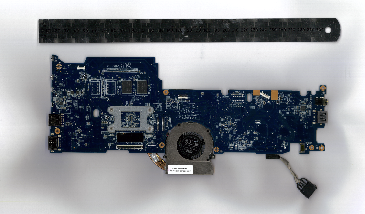
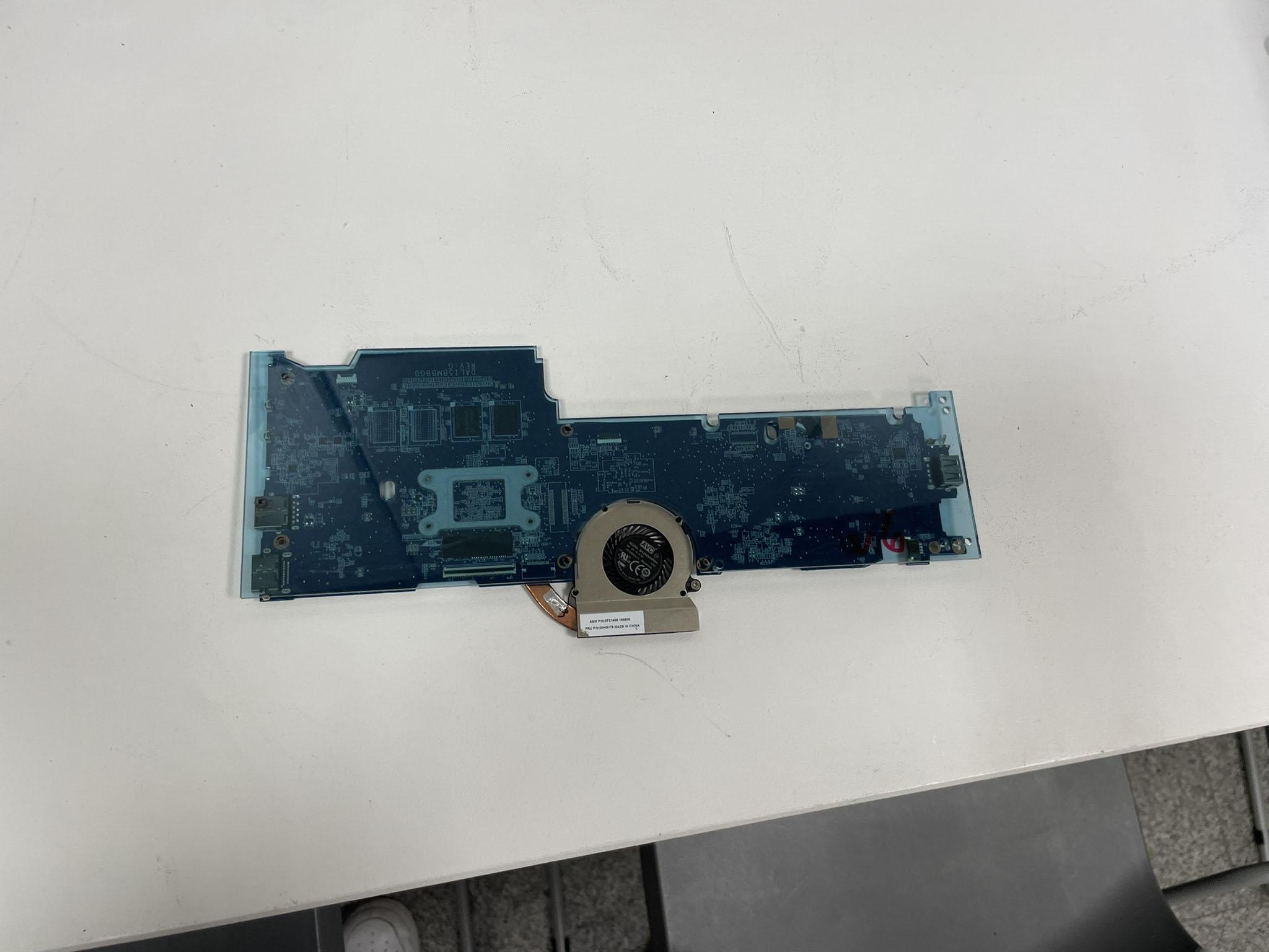
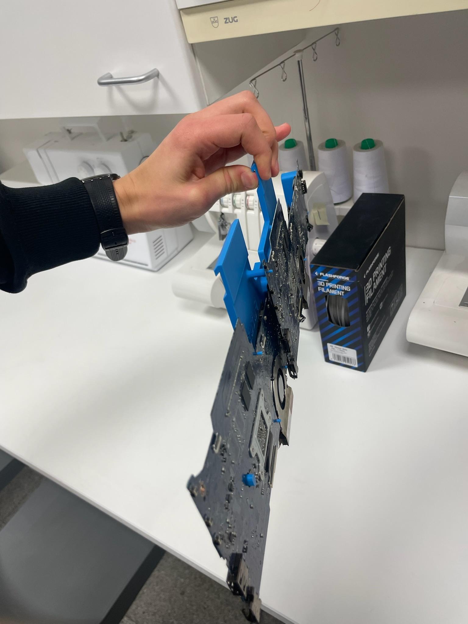
Taking apart one of the Chromebooks, while carefully avoiding the battery, there were only two main parts that we needed for them to function away from the casing: the motherboard and the screen.
Definitely performed by professionals, do not try at home.
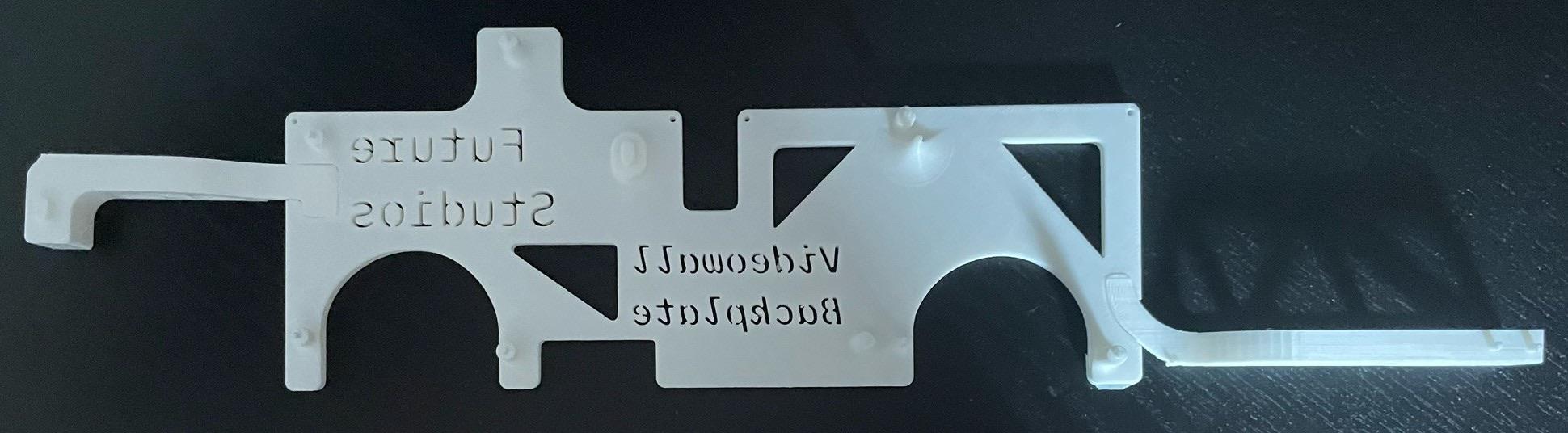
Since our project relied on holding up the deconstructed motherboards, we needed to create a 'backplate' to attach the motherboard and screen to.
For the first iteration, we just wanted to get a good digital layout of the motherboard. A neat trick I used was to scan the motherboard with a ruler, allowing you to scale the image digitally with a reference to the correct dimensions.
Using Illustrator to trace and create holes where the screws used to go, I laser cut a rough acrylic backplate.
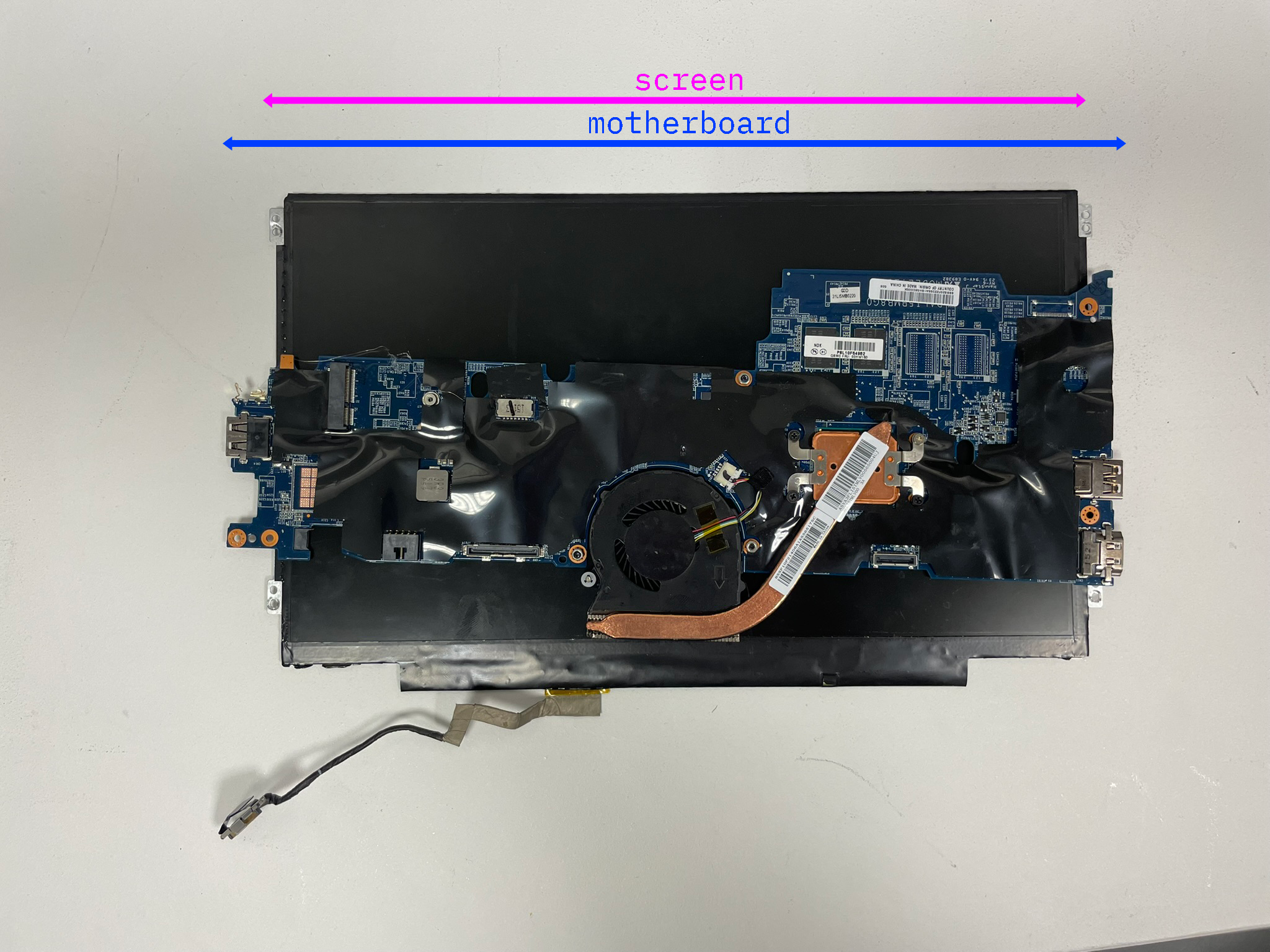
Unfortunately, I quickly realized that simply using acrylic pieces wouldn't work, as the motherboards are longer than the screen itself. This meant that placing multiple backplate sets in a line led to large gaps between the screens as the motherboards would physically clash with each other.
Boo.
I had to rethink my approach. Due to the short length of the screen's connector, I couldn't place the motherboards in a way that they wouldn't hit each other, and I didn't want the motherboards to be below the screen. So, I decided to try and create a two-screen module that supported two motherboards partially on top of each other to solve this length issue.
Computer Aided Discomfort (CAD)
My experience with 3D modeling prior to this project was Tinkercad, a simple browser-based modeler that I'd used for small projects, and Blender, a more artistic 3D modeling software. Unfortunately, neither of these was sufficient for a project of this complexity.
Thus, I decided to learn Autodesk Fusion 360, which, while confusing at first, allowed me to create dimensionally accurate prototypes with much better precision than Tinkercad or Blender.
After printing off the first 3D printed version, I slotted two motherboards through their respective pegs and…
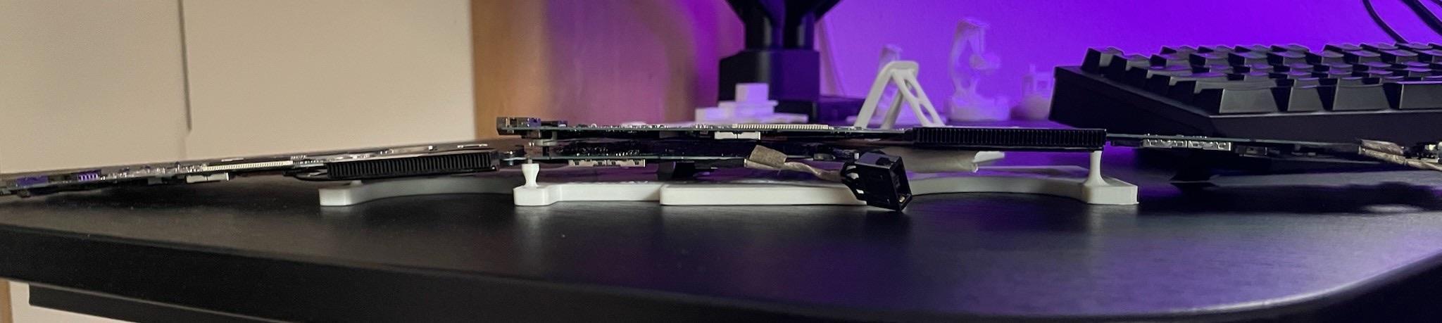
That's a pretty dramatic sag.
Unfortunately, the printer I was using wasn't able to print a backplate long enough to support the entirety of the two motherboards, leading the ends to sag heavily.
While I fixed this issue pretty quickly by adding separately printed pieces, over the next few weeks I encountered issue after issue. I'd print a new version to fix a problem, realize I had another issue, and have to print a whole new version, only to realize that I'd created a brand new problem.
Separately printed clips to solve the sagging issue.
Later, I changed the add-on pieces to attach via a clip system so I could remove pieces if need be. After many, many iterations, I finally settled on a design to hold both motherboards.
The Screens
Now onto the actual screens themselves — while having a row of motherboards hanging on their own is pretty, it isn't what we want.
Following the same scan method I used for the backplate, I recreated the screens inside of Fusion 360, allowing me to build an accurate retaining frame to hold them to the backplate.
I used the same clips as I had for the additional pieces to attach the screen holder, which led to many frustrating attempts to try and put the pieces together, only for them to snap.
This happened so many times.
Instead of making a new clip that would be easier to attach without the risk of breaking, I took the easy route and ignored the issue (there might be a lesson in there somewhere). I continued to make the final touches to the design, such as adding cable channels to clean up the overall look of the backplate. Even though almost no one would see it, I wanted it to look as good as possible.
For attaching it to the wall, we used a French cleat system which allowed the individual parts to be easily removed and serviced if needed. Doing some quick tests with tape, the project held well.
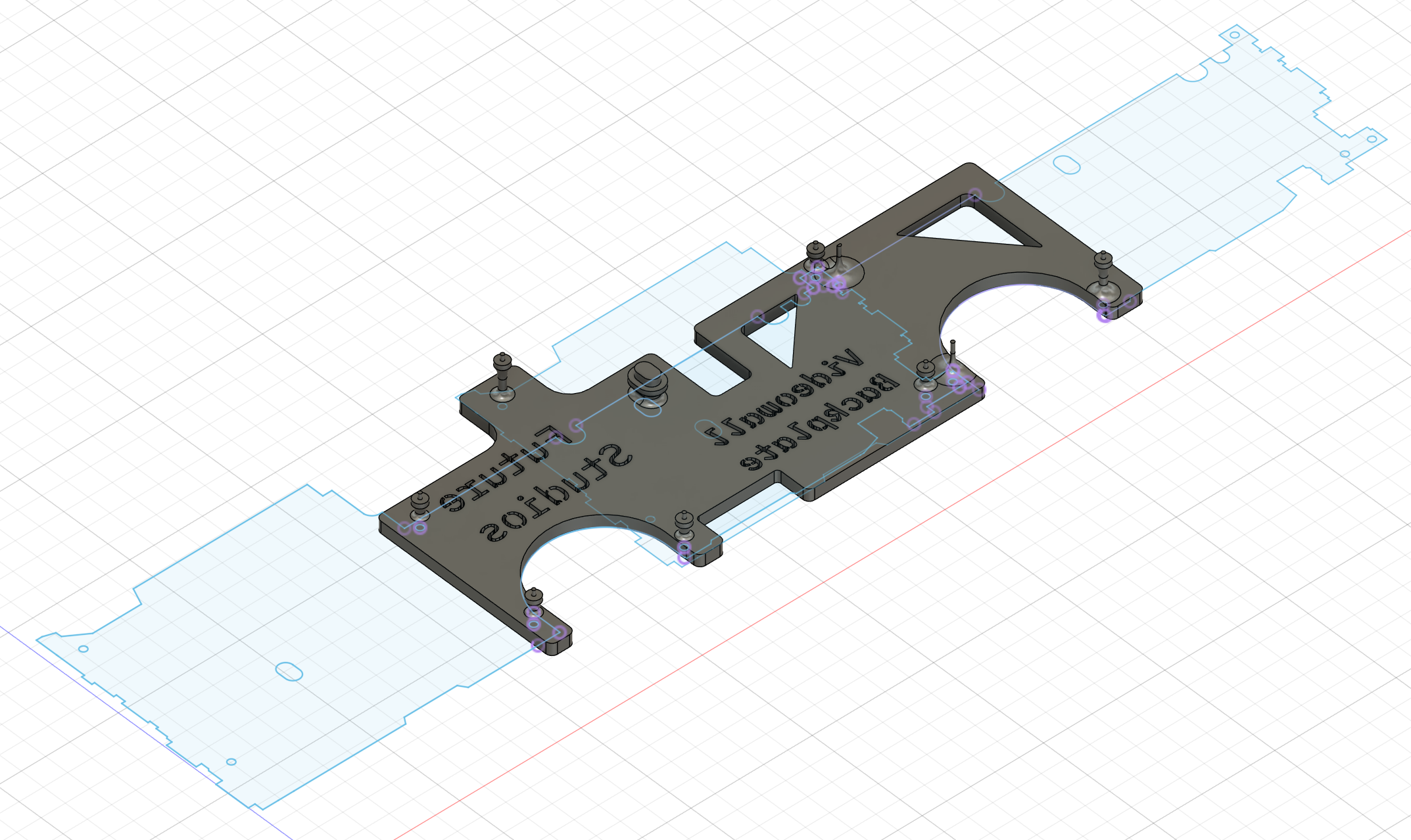
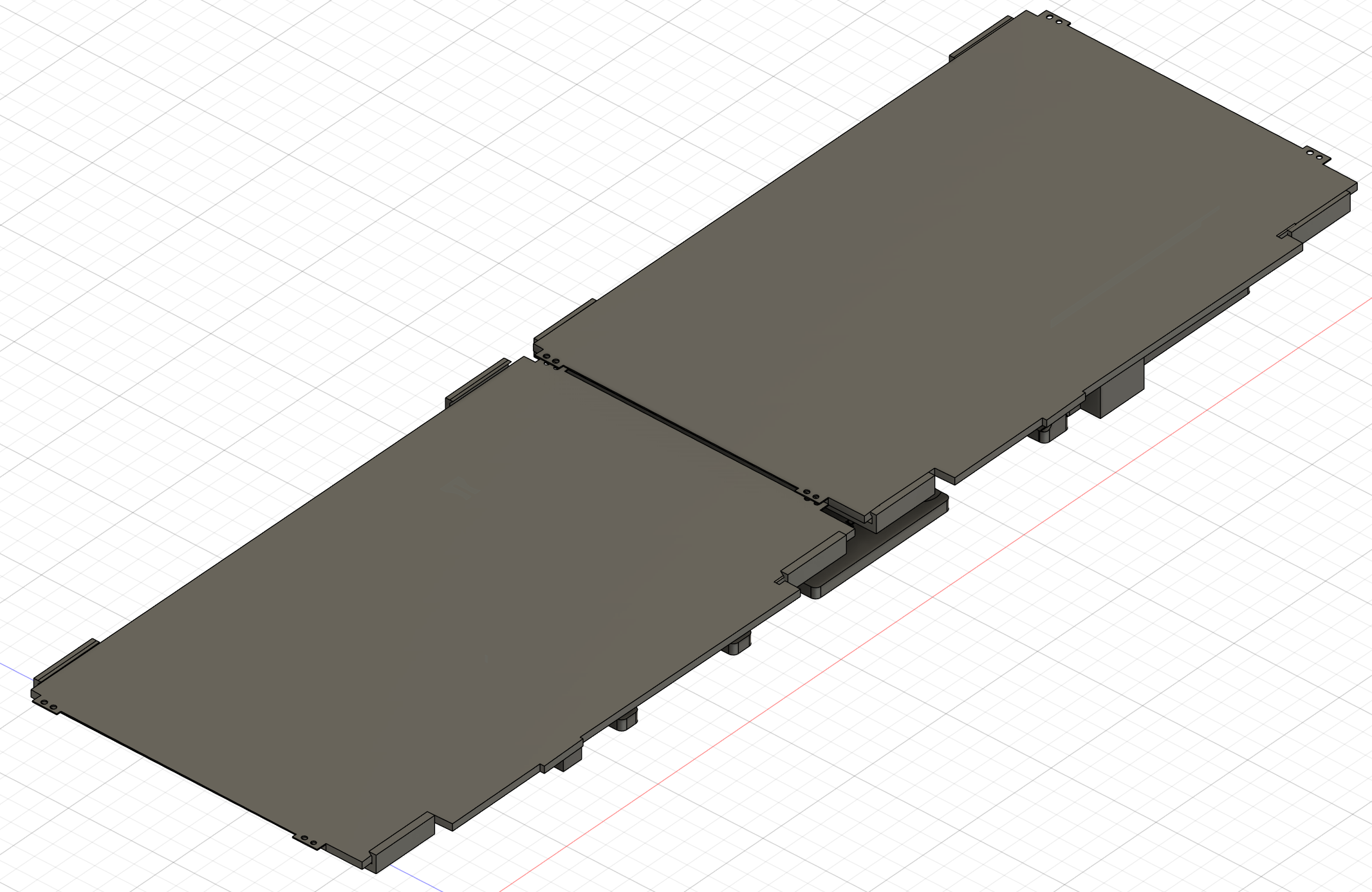
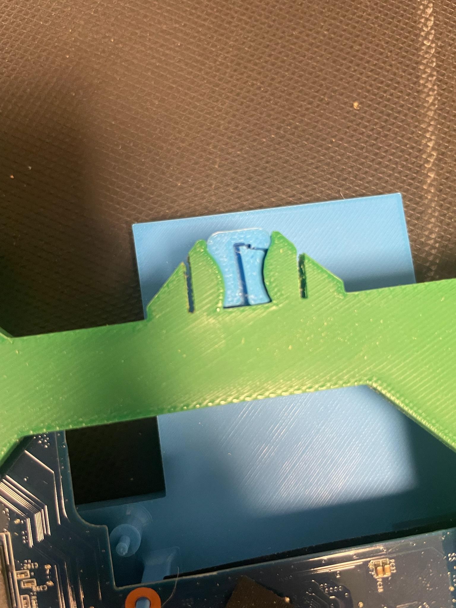
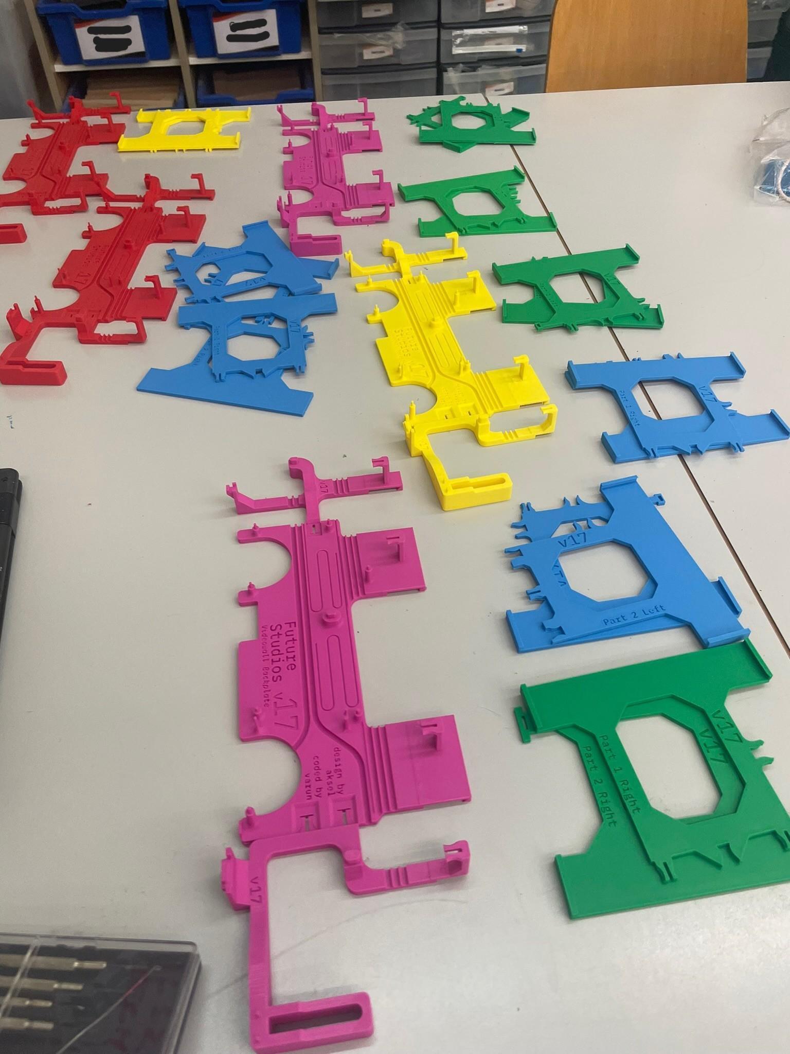
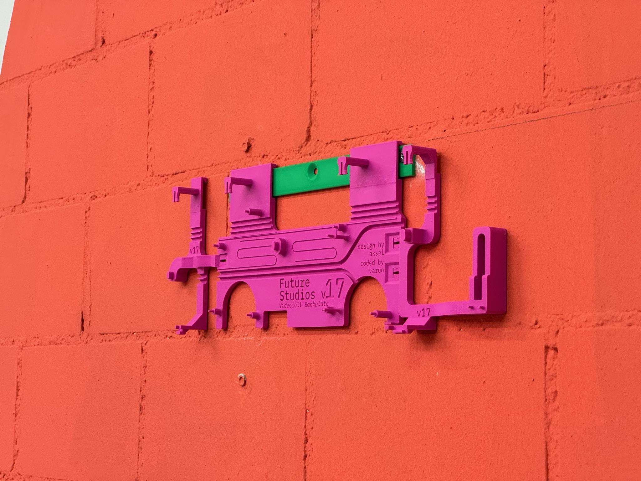
Finally, after many many iterations in Fusion 360 (120+!), the final CAD files were finished.
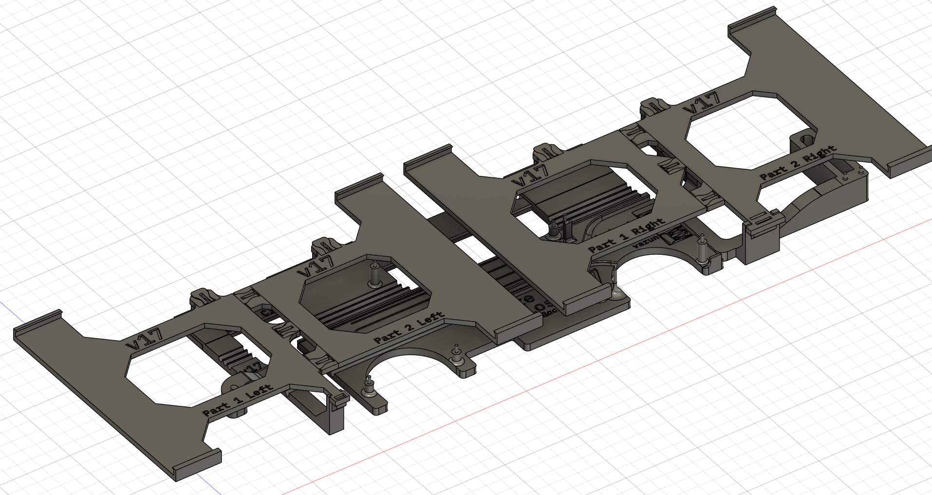
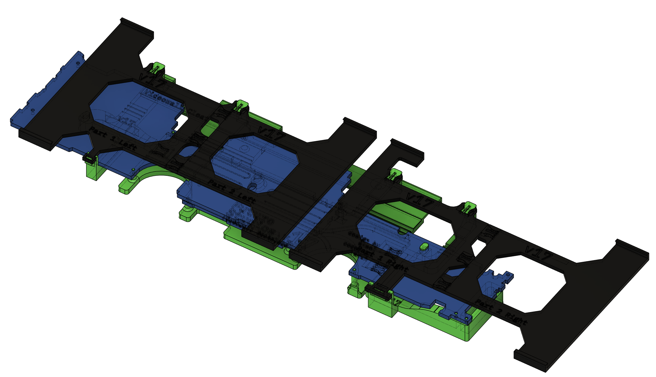
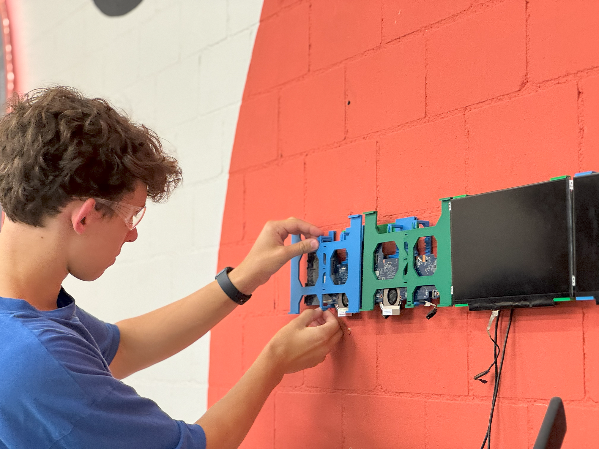
Green: Main backplate — Blue: Motherboard — Black: Screen holder(s).
Doing some sketchy cable splicing (first time soldering and it's on power cables, yay!), we could power two motherboard–screen pairs with one cable.
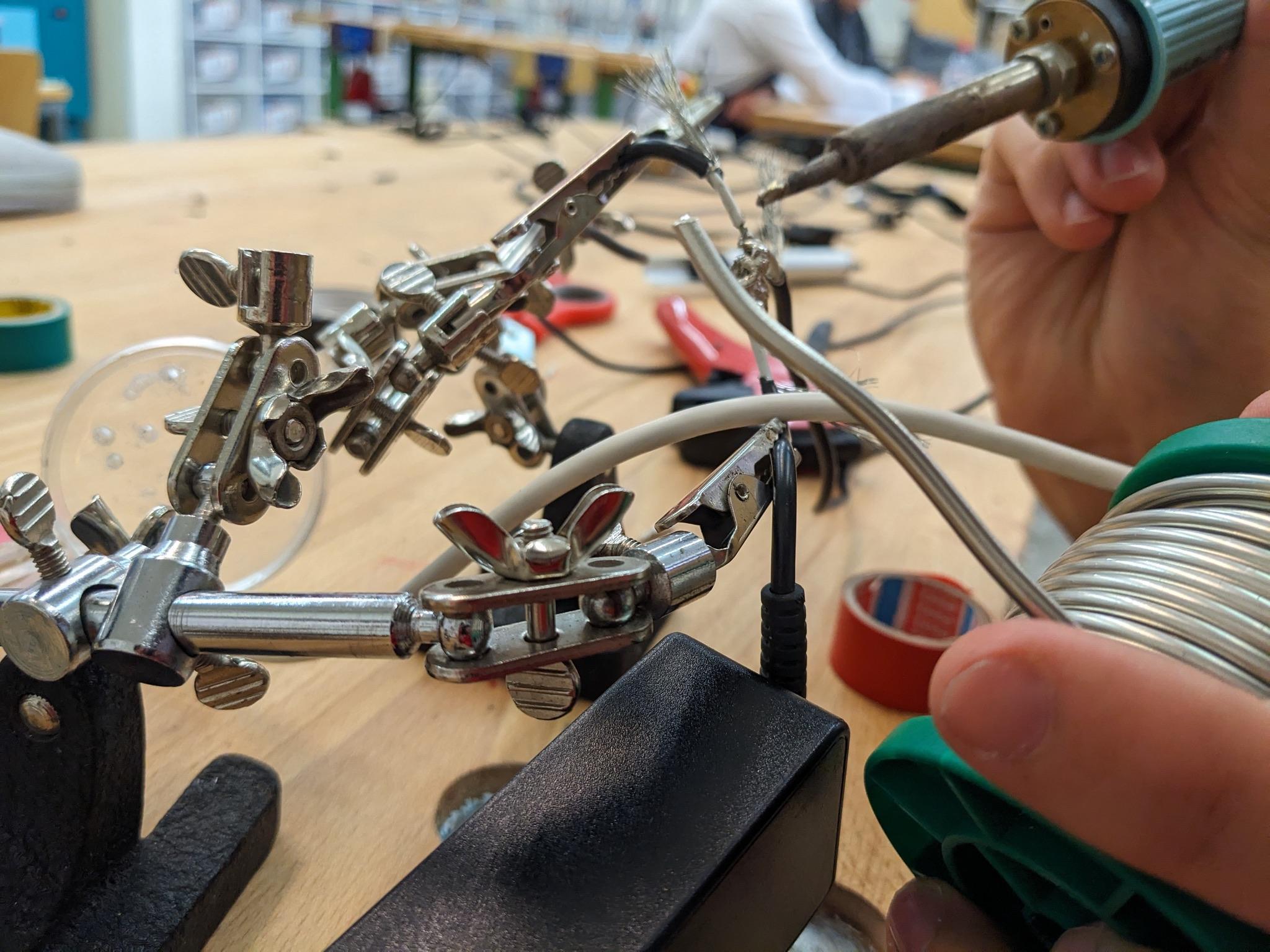
I think it's pretty clear it's my first time doing this.
The Final Stretch
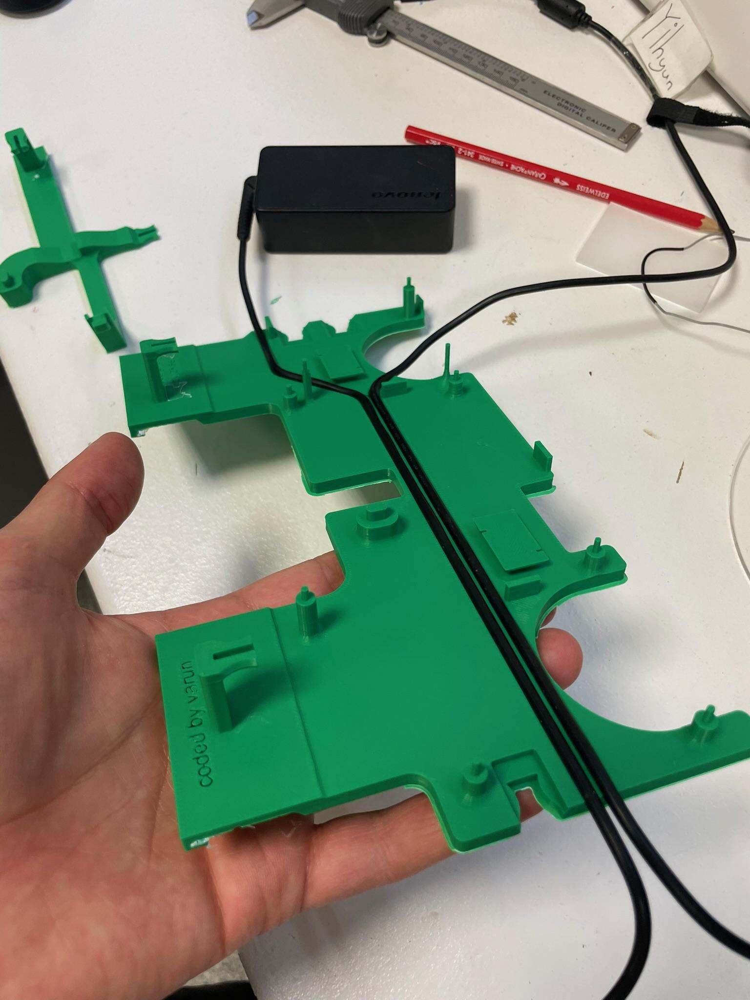
Printing everything off, we now just had to assemble everything.
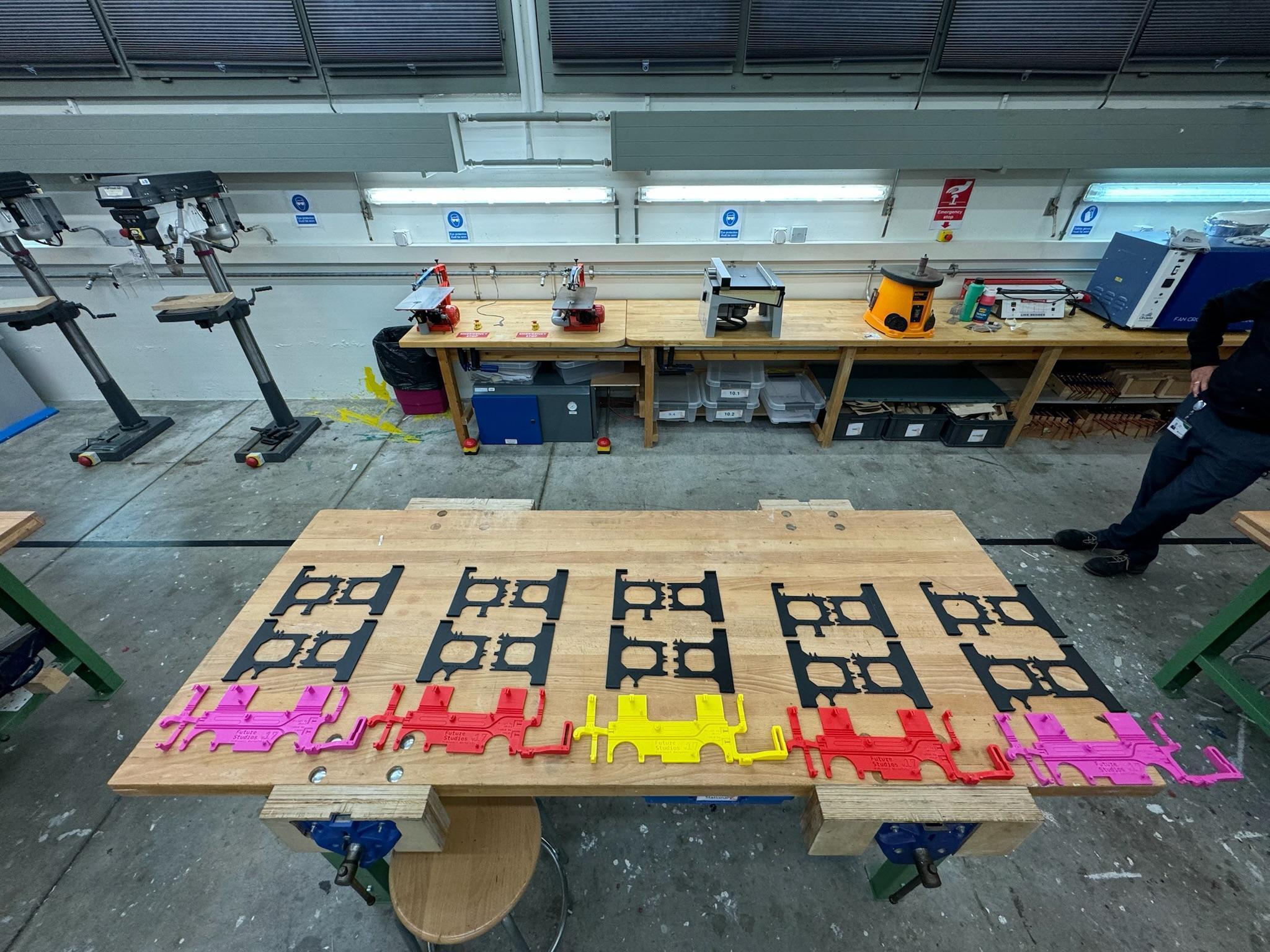
Taking some picturesque photos…
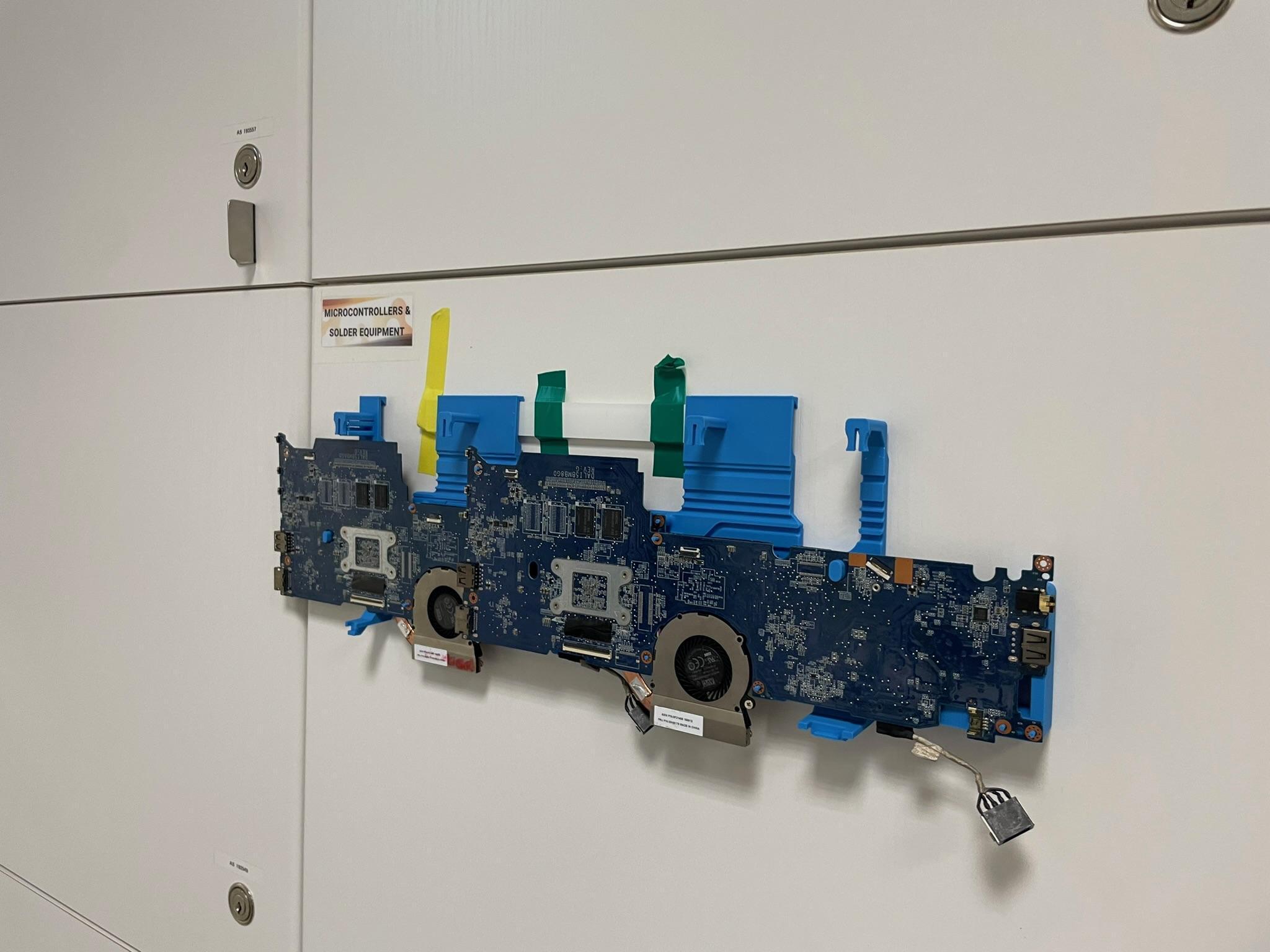
We hung all the motherboards and their screens on the wall.
After ensuring everything worked and replacing a few scratched screens, we cleaned up the cables and added a border.
Over two years after starting this project, we were finally finished.
Thank you very much to Varun; without him, this project would never have been possible, and I would have never wanted to do it. Our design teacher and mentor, Mr. Bush, also played a massive role in pushing us to do the project in the first place, and I can't thank him enough for being an inspiration to get into design in the first place.
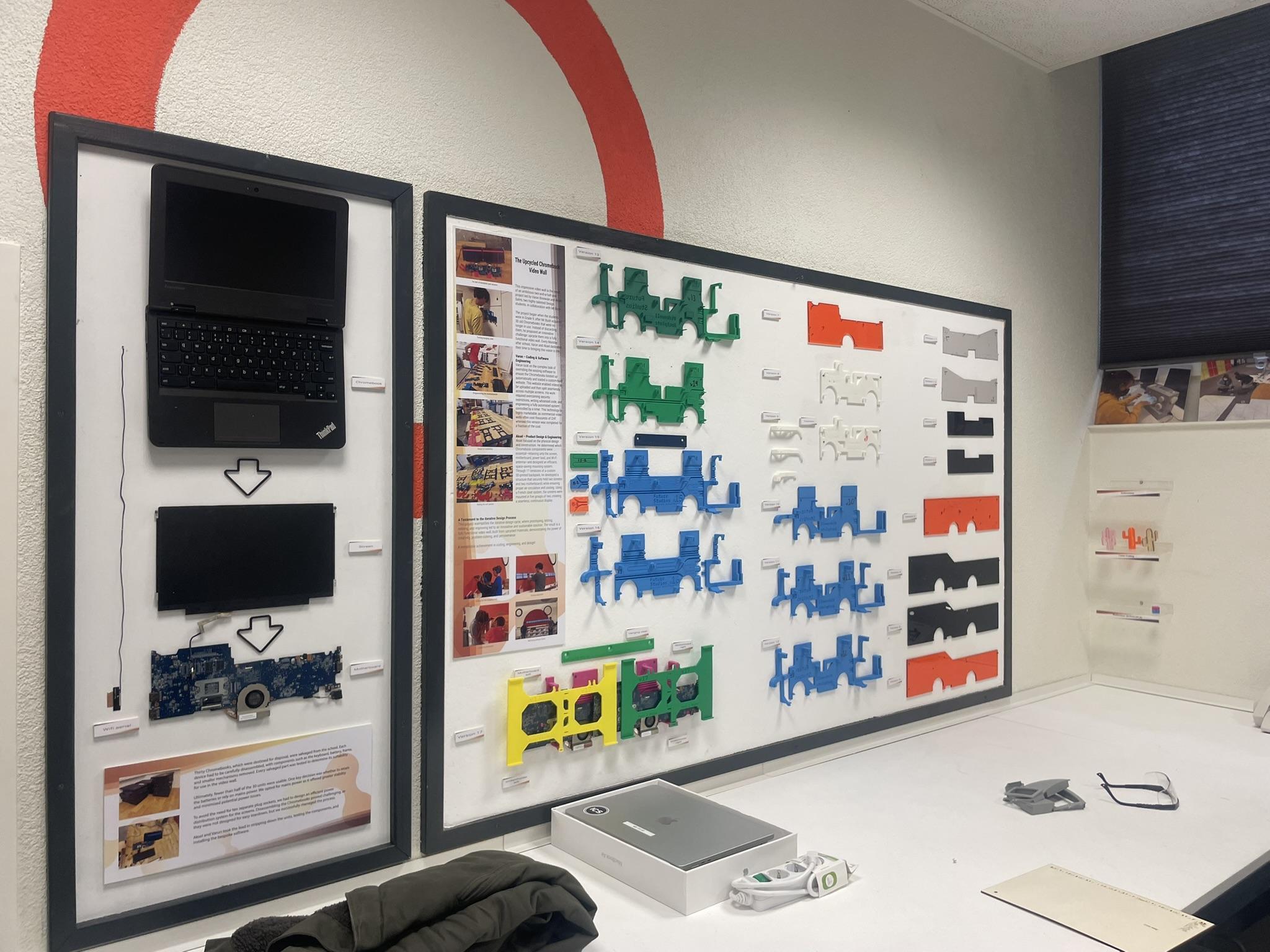
A display created by our mentor showcasing the variations and process of the project.
If you would like any of the files, feel free to reach out.